 |
||||
Providing Switch protection for the worlds rail systems |
||||
 |
||
SPECIFICATIONS |
|
Main Processing Module Supply Power: 8 to 24 VDC @ mA nominal reverse polarity protected. Inputs: 7 Inputs rated for 5 to 24 vdc @ 10 mA with LED Indicators Terminals 7, 8 and 9 = B12 Terminals 4, 5 and 6 = N12 Terminal 10 = Wheel count reset
Outputs: 3 Outputs sourcing 7 to 24 vdc based on the supply power each rated for 50 mA maximum to drive external circuitry or relays with LED indication. Terminal 1 = Throw Enable (Maintained) Terminal 2 = Auto-Line Reverse (Momentary) Terminal 3 = Auto-Line Normal (Momentary)
PC Connection PC connection for programming and diagnostics. Operating Condition: Ambient Temperature –40 Degrees C to + 85 Degrees C (-40 Degrees F to +185 Degrees F). Circuitry is housed and potted in a plastic enclosure to prevent Moisture Interference.
Physical Dimensions: 4.0” Tall x 3.1” Wide x 1.0” Thick |
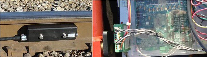
Wheel Sensor Module
Supply Power: 8to 24 VDC @ 32 mA nominal. Reverse polarity protected.
Sensing Range: Optimum performance is achieved with the sensor placed at 1.75” below top of rail.
Maximum Distance of wheel sensors from the Main Module: 2000 Ft., using 18 AWG twisted pairs.
Operating Conditions: Ambient Temperature –40 Deg. C to +85 Deg. C (-40 Deg. F to +185 Deg. F) Totally encapsulated and sealed to withstand shock vibration, chemicals and water at typical railway environment.
Physical Dimensions: 9.7” Long x 1.75” Thick x 2.8” Tall
Mounting Options: Two (2) through holes are provided for attachment to the bolt on bracket manufactured by Railway Technology Inc. or direct connection using spacer to the rail via 3/8” bolts. |
|||
Copyright 2010 Rail Switch Service, LLC |
|||